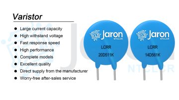
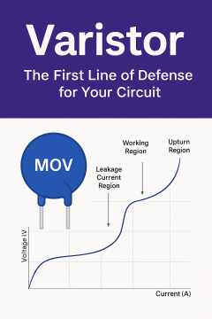
Applications of Varistors in Electronic Products
As electronic te...

The main characteristic of a thermistor is its sensitivity to temperature—its resistance varies with changes in temperature.

1. Classification of thermistors
Positive Temperature Coefficient (PTC) Thermistor: Its resistance increases significantly with rising temperature. This property makes PTC thermistors suitable for resettable fuses and heater applications.
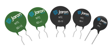
Negative Temperature Coefficient (NTC) Thermistor: Its resistance decreases significantly as the temperature rises. This property allows NTC thermistors to be used in temperature compensation, temperature control systems, and inrush current limiting.

2. Parameters of thermistors
① Rated Zero-Power Resistance R<sub>25</sub> (Ω):
According to national standards, this is the resistance value of an NTC thermistor measured at a reference temperature of 25°C with zero power applied. It is the nominal resistance of the thermistor. When people refer to the resistance value of an NTC, they usually mean this value.
② Thermal Constant B Value (K):
Defined as the ratio of the natural logarithm of the resistance at two temperatures to the difference in the reciprocals of those two temperatures. Once determined, the B value is fixed. For typical NTC thermistors, B values range from 2000K to 6000K. A higher B value indicates a greater resistance change with temperature variation.
③ Dissipation Factor (δ):
Under specified ambient temperature conditions, the dissipation factor of an NTC thermistor is the ratio of the change in power dissipated to the resulting change in the thermistor’s body temperature.
④ Thermal Time Constant (T):
Under zero-power conditions, it is the time required for the thermistor’s temperature to change by 63.2% of the total difference between the initial and final temperatures following a sudden temperature change. The thermal time constant is directly proportional to the thermistor's thermal capacity and inversely proportional to its dissipation factor.
⑤ Rated Power (P):
The maximum power the thermistor can continuously dissipate under specified technical conditions without exceeding its maximum operating temperature.
⑥ Maximum Operating Temperature (T<sub>max</sub>):
The highest temperature at which the thermistor can operate continuously under specified technical conditions.
3. Thermistor circuit application
NTC thermistors are generally divided into two application types: temperature-sensing thermistors (Example 1) and power thermistors (Example 2).
Example 1: Thermistor Temperature Sampling Circuit

Example 2: Surge current protection (NTC is widely used in power input)

As shown in the diagram: RT1 to RT4 indicate common thermistor positions.
For dual-voltage input products (110Vac and 220Vac), it is recommended to place two NTC thermistors at positions R1 and R2. This ensures consistent inrush current suppression for both voltages.
For single-voltage 220Vac products, placing a single NTC at either R3 or R1 is sufficient.
Operating Principle:
Due to the presence of bulk capacitors, powering on causes a large inrush current. By placing an NTC thermistor in series at the input, its high initial resistance (at room temperature) effectively suppresses this surge.
As the current flows, the thermistor quickly heats up, and its resistance drops to a very low level—typically in milliseconds—down to a few ohms or less. This has negligible impact on normal operation and power consumption.
Compared to fixed resistors, this results in dozens to hundreds of times lower power loss, making it ideal for energy-efficient and high-efficiency products such as switching power supplies.
After power-off, the NTC thermistor cools down and its resistance gradually returns to its rated zero-power resistance. The recovery time ranges from several tens of seconds to a few minutes, after which it is ready for the next power-on cycle.


Company:Jaron NTCLCR Microelectronics
Website:www.jaronsemi.com
WhatsApp:+86 199 2921 8123
+86 136 5494 8860
Email:jaron@ntclcr.com
Address:Room 619-620, Zhenqian Building, No. 80 Gongye Road, Longhua District, Shenzhen, Guangdong, China