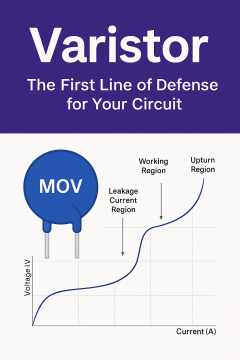
Varistor: A Key Component in Circuit Protection
Introduction to Metal Oxide Va...

The MF72 is a negative temperature coefficient (NTC) power thermistor designed for high-voltage endurance, high current capacity, and fast response. Its primary function is to suppress inrush current during the startup of electronic devices, thereby protecting circuit components. Its key advantages include:
High Energy Absorption:
Capable of withstanding transient surge currents ranging from several tens to hundreds of amperes.
Self-Recovery Characteristic:
Quickly returns to its nominal resistance at ambient temperature, ensuring normal device operation.
Wide Temperature Adaptability:
Operates efficiently over a typical temperature range from –40°C to +150°C, with certain upgraded models rated up to +200°C.
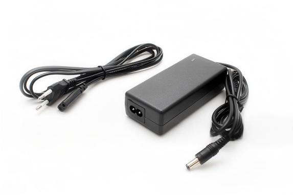
Switch-Mode Power Supplies/UPS:
Function: Suppress the surge current generated during capacitor charging at startup, protecting the rectifier bridge and electrolytic capacitors.
Example: In a 1 kW switch-mode power supply, incorporating an MF72-5D15 (with R25 = 5Ω) in series can reduce a surge current from 200 A to below 20 A.
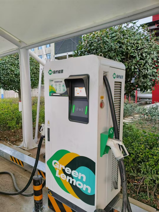
Inverters/Charging Stations:
Deployed at the DC bus input to prevent capacitor charging shocks and extend the lifespan of relays.
Industrial Motors/Compressors:
Mitigates stall currents during motor startup, thereby avoiding damage (e.g., contact burning on relays).
Selection Consideration: Choose the R25 value based on the motor's rated power; for example, a 3 kW motor may be paired with an MF72-10D9 (R25 = 10Ω with a steady-state current of 5 A).
LED Power Supplies:
Reduces startup current spikes in high-frequency drive circuits, protecting critical components such as MOSFETs and ICs.
HID Lamp Electronic Ballasts:
Limits current surges during cold starts, thus preventing electrode sputtering.
Photovoltaic Inverters:
Provides reverse polarity protection on the DC side and suppresses surge currents when battery banks are connected.
Electric Vehicle Charging Modules:
Prevents inadvertent fuse triggering by mitigating the instantaneous charging of large-capacity capacitors.
Zero-Power Resistance (R25):
Calculation Formula:
R25 ≥ U<sub>peak</sub> / I<sub>s surge</sub>
Example: With an input voltage of 310 V DC and a permissible surge current of 50 A, the R25 must be at least 6.2Ω (thus, select MF72-8D15).
Steady-State Current (I₀):
The selected model should have a steady-state current rating exceeding the continuous operating current of the equipment. For instance, for a 5 A circuit, choose a thermistor with I₀ ≥ 7 A (providing approximately a 30% margin).
Maximum Current (I<sub>max</sub>):
In accordance with IEC 61051 standards, the thermistor’s current rating should cover at least 50% of the device’s short-circuit current.
Cooling Conditions:
Under natural convection, the surface temperature of the MF72 should remain below 120°C. Forced air cooling can enhance the current carrying capacity by approximately 20%.
Residual Resistance (R<sub>res</sub>):
Preferably, select models with R<sub>res</sub> less than 5% of R25 (for instance, the Koya MF72-XX series) to reduce overall power loss.
| Model |
|
Typical Application Area | |||
| MF72-3D9 |
7.5 |
|
|||
| MF72-10D25 | 20 |
|
|||
| MF72-5D15 (SMD) | 5×5 |
|
4. Common Selection Pitfalls and Strategies for Enhancing Reliability
Overreliance on R25 Value:
Focusing solely on the R25 specification while neglecting thermal equilibrium can result in ineffective surge protection during repeated startups.
Neglecting Aging Characteristics:
Under prolonged high-temperature operation, the MF72’s B value may drift by ±10%, necessitating periodic inspection and testing.
Redundant Design:
Consider paralleling TVS diodes to manage extreme surge events (e.g., during lightning strikes).
Iterative Model Selection:
High-Temperature Environments: Utilize the glass-encapsulated MF72G series, rated for up to +200°C.
High-Frequency Environments: Choose the MF72-F series, designed with low inductance (<50 nH) for improved performance.
Step 1: Requirement Analysis
Input Voltage: AC 380 V
Maximum Surge Current: 120 A (measured value)
Operating Temperature Range: –20°C to +85°C
Step 2: Parameter Calculation
R25 Calculation:
R25 ≥ (380 V × 2) / 120 A ≈ 4.47Ω, rounded to a selection of R25 = 5Ω.
Steady-State Current Determination:
With the inverter’s rated current at 8 A, select a thermistor with I₀ ≥ 10 A.
Step 3: Model Lock-In
Selected Model:
MF72-5D15 (R25 = 5Ω, I₀ = 15 A, with a 15 mm diameter), supplemented by an appropriate heatsink.
Step 4: Verification Testing
Surge Suppression Test:
Oscilloscope measurements confirm that the startup current peak is within the specified limit (≤25 A).
Thermal Rise Test:
After 2 hours of full-load operation, the surface temperature remains at or below 95°C, meeting performance criteria.


Company:Jaron NTCLCR Microelectronics
Website:www.jaronsemi.com
WhatsApp:+86 199 2921 8123
+86 136 5494 8860
Email:jaron@ntclcr.com
Address:Room 619-620, Zhenqian Building, No. 80 Gongye Road, Longhua District, Shenzhen, Guangdong, China