Varistor: A Key Component in Circuit Protection
Introduction to Metal Oxide Va...

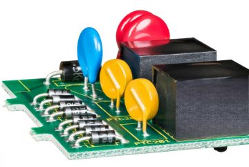
MOV (Metal Oxide Varistor) is one of the most widely used overvoltage protection devices. Its core material is a polycrystalline semiconductor sintered by zinc oxide (ZnO) and additives. The following is a systematic analysis from the principle, parameters, selection to application:
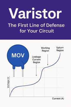
1.1 Nonlinear Volt-Ampere Characteristics
Low Voltage Region: When the voltage is below the threshold, the MOV remains in a high-resistance state (leakage current is in the microampere range).
Breakdown Region: Once the voltage exceeds the threshold (nominal voltage Vn), resistance drops sharply, allowing large current to discharge, achieving voltage clamping.
Clamping Voltage (Vc): Typically 1.5 to 2 times the nominal voltage, ensuring it stays below the voltage rating of the protected components.
1.2 Materials and Structure
Zinc Oxide Base: ZnO grains and grain boundaries form a "PN junction-like" barrier, providing a fast response (nanosecond-level).
Multilayer Structure: The dense ceramic body, formed through sintering, correlates current-carrying capacity with volume. For example, the 14D series with a 14mm diameter can withstand surge currents up to 10kA.
2.1 Nominal Voltage (Vn)
Definition: The voltage at 1mA DC current (e.g., 470V).
2.2 Selection Formula:
AC System: Vn ≥ 1.2–1.5 × RMS supply voltage (e.g., 220V AC selects 470V).
DC System: Vn ≥ 1.5 × maximum continuous operating voltage.
Misconception: The nominal voltage is not the "trigger voltage"; actual turn-on voltage may be higher (refer to the V-I curve).
2.3 Peak Current (IP)
Definition: The peak current for an 8/20μs standard surge waveform (e.g., 10kA).
Application Level:
|
Application Scenario |
Recommended IP value |
Packaging Example |
|
Consumer Electronics |
3~5kA |
SMD 0805/1206 |
|
Industrial Power Supply |
10~20kA |
Plug-in 14D/20D |
|
Outdoor lightning protection |
≥40kA |
Large size (34D, etc.) |
2.4 Energy Handling (Joule)
Formula: E = Vc × IP × t (where t is pulse width, typically 20μs at 8/20μs).
Example: With Vc = 800V and IP = 10kA, the energy is 160J. Ensure the MOV’s rated energy exceeds the actual surge energy.
2.5 Failure Modes and Lifetime
Aging Failure: After multiple surges, leakage current increases, and ultimately, the MOV may short-circuit.
Safety Design: Use temperature fuses (TF) or MOVs with thermal trip mechanisms (e.g., TNR series) to prevent short-circuit-induced fires.
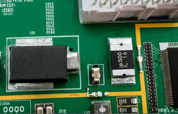
3.1 Circuit Layout
Proximity Installation: Place MOVs close to the protected end (e.g., power inlet) to shorten surge paths.
Low-Inductance Wiring: Avoid long traces that add parasitic inductance, which can increase residual voltage.
Parallel decoupling: When used with a gas discharge tube (GDT), a series resistor or inductor is required to prevent the GDT from continuing current and causing the MOV to burn out.
3.2 Multi-Level Protection Design
Level 1 Protection (Leakage): Gas Discharge Tubes (GDT) or spark gaps, to discharge lightning currents.
Level 2 Protection (Clamping): MOVs reduce residual voltage to below 1kV.
Level 3 Protection (Precise Protection): TVS diodes further clamp voltage to a safe level for sensitive chips (e.g., 24V).
Typical Design: GDT (Level 1) → MOV (Level 2) → TVS (Level 3).
3.3 Thermal Management and Derating
High-Temperature Derating: MOVs’ current-carrying capacity decreases by about 20% for every 25°C increase in ambient temperature.
Parallel MOVs: For high-energy applications, parallel multiple MOVs with matched parameters (e.g., Vn deviation ≤5%).
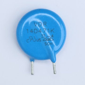
4.1 Home Appliances (220V AC)
Requirement: Surge suppression for grid surges (e.g., air conditioner start/stop).
Selection: 14D471K (Vn = 470V, IP = 6.5kA), SMD option: S14K275.
4.2 Photovoltaic Inverters (DC 1000V)
Requirement: Lightning protection on the photovoltaic panel side, withstands high voltage.
Selection: 34D102K (Vn = 1000V, IP = 40kA).
4.3 Automotive Electronics (12V/24V Systems)
Requirement: Surge suppression for load dump to 60V.
Selection: SMD type V14H360 (Vn = 36V, IP = 200A).
5.1 Excessive Leakage Current in MOV
Cause: Aging or sustained over-voltage, degrading grain boundaries.
Solution: Regularly replace MOVs or use TVS diodes to share voltage stress.
5.2 High Residual Voltage Damaging Post-Circuit
Cause: Incorrect MOV selection (e.g., overly high Vn) or improper layout.
Solution: Lower Vn or add a TVS for secondary clamping.
5.3 MOV Frequent Failure
Cause: Insufficient peak current handling or exceeding surge frequency.
Solution: Upgrade IP rating or implement multi-stage protection to share energy.
Safety Certifications: UL1449 (Surge Protective Devices), IEC 61000-4-5 (Surge Immunity Test).
Automotive Electronics: AEC-Q200 (Reliability Certification), performance in the –40°C to 150°C temperature range.
Telecommunication Equipment: GR-1089-CORE (Lightning and ESD Protection Requirements).
Summary: MOV has become a core device for overvoltage protection due to its high cost-effectiveness and large current capacity, but it needs to be accurately selected according to the application scenario and combined with multi-level protection and heat dissipation design to achieve reliable protection. In actual design, it is recommended to verify the effectiveness of the solution through surge testing (such as 8/20μs, 10/700μs).
Company:Jaron NTCLCR Microelectronics
Website:www.jaronsemi.com
WhatsApp:+86 199 2921 8123
+86 136 5494 8860
Email:jaron@ntclcr.com
Address:Room 619-620, Zhenqian Building, No. 80 Gongye Road, Longhua District, Shenzhen, Guangdong, China